Sliding gate fittings - C profiles
Classic 9 - Tube drives - C profiles
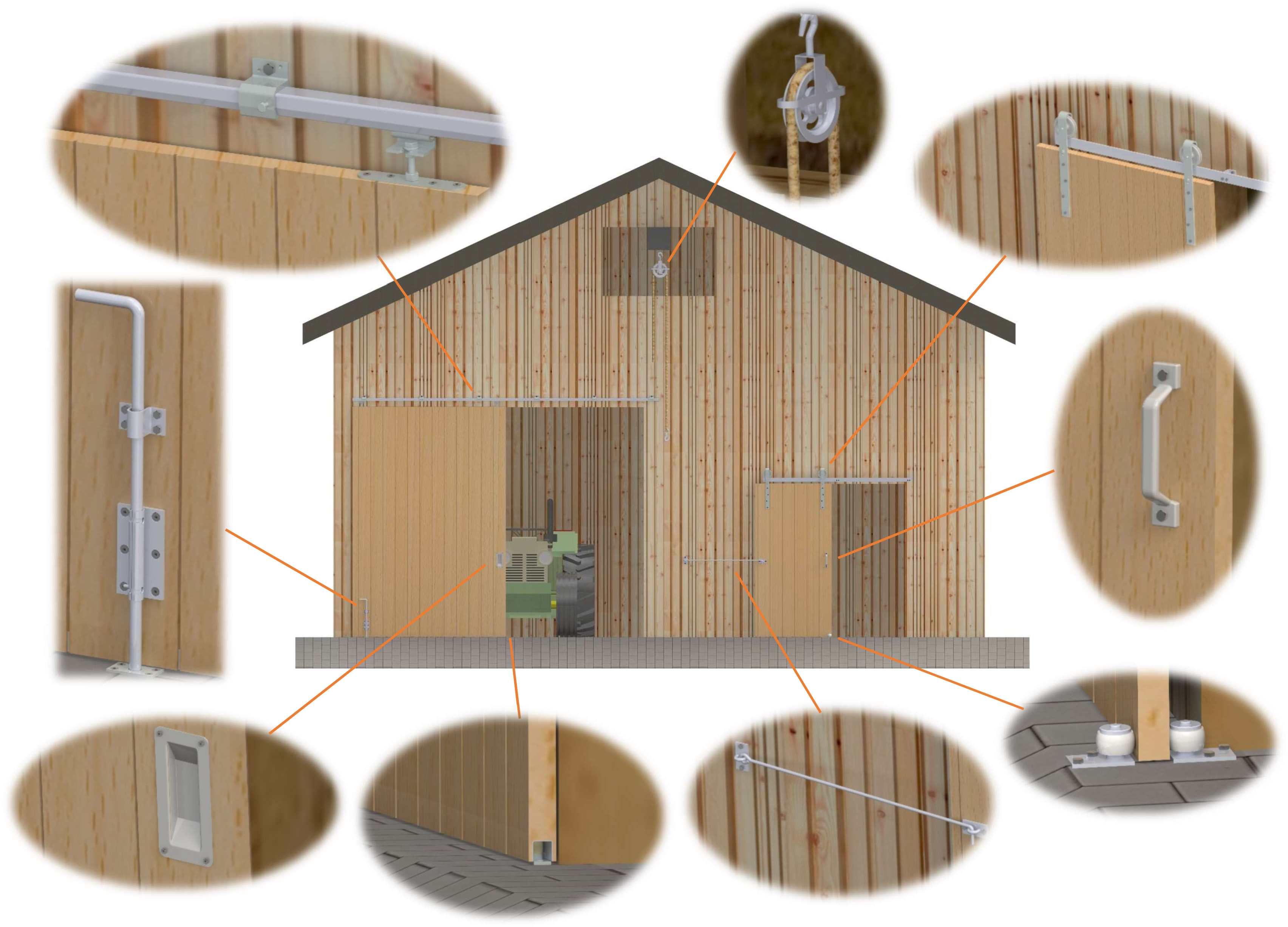
In our product range you will find fittings you will need for installation of a sliding gate.
Using our type-colour code system in our catalogue, you can quickly and easily match the corresponding fittings.
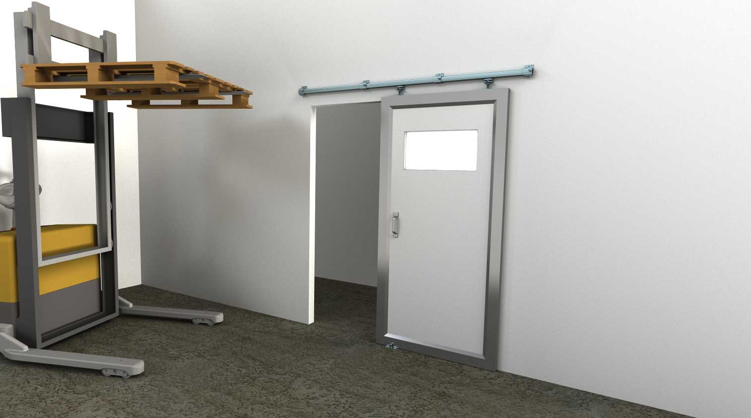
Generally, a sliding gate requires a track with fastening sleeves, roller apparatus for guiding the gate leaf in the track, track door stoppers to limit the driveway of the reel module and a bottom guide.
It is also advisable to use screw plates or brackets to attach the reel module to the gate leaf. Furthermore, we recommend careful selection of the fitting material when planning a sliding gate.
We offer fittings made of steel, stainless steel (V2A or V4A) and aluminium. Our steel tracks are galvanized with a zinc-magnesium coating, making them suitable for outdoor use.
You need 3D drawings for your planning or construction?
We would be happy to assist you!
Our fittings would be the perfect addition to your specialized retail assortment. We have the ideal solution for your sales area!
If you want more information, please feel free to use our contact form and also take a look at our sliding gate configurator.
Sliding gate C profiles (Classic 9)
In gate construction - and especially with sliding door fittings - the quality of the fittings is crucial.
Therefore, we recommend long-term planning. Experience shows that it is worthwhile to make a substantial investment initially to benefit sustainably afterwards.
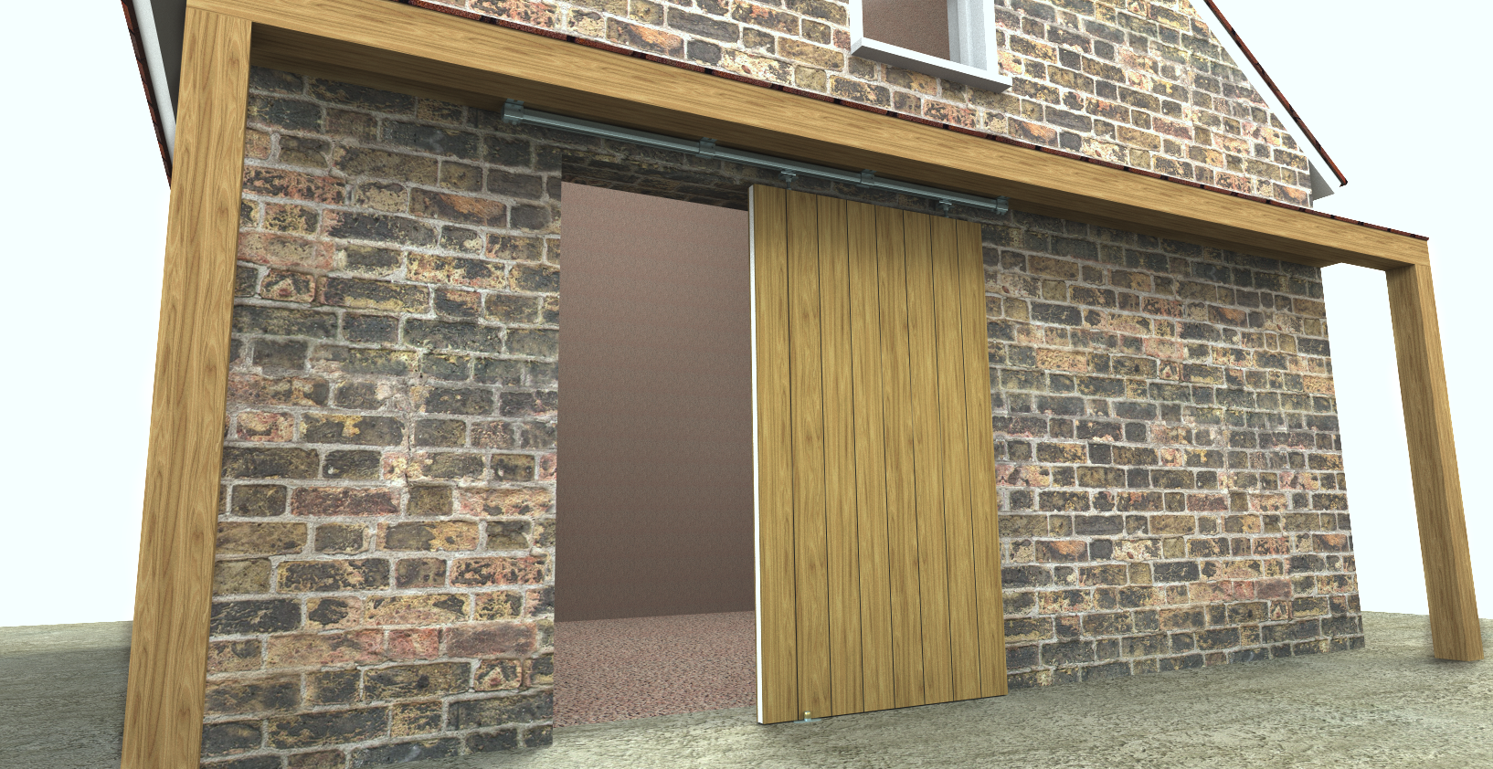
From our versatile system range, you can choose the right fittings with a long lifespan for your sliding gate project. By the way, our sliding door fittings are very low-maintenance even in the dusty daily environment of a barn or hayloft.
Trust in our more than hundred years of expertise and decide for our smooth-running and proven sliding door fittings, including matching accessories.
Inferior quality of fitting components often leads to high wear and tear, resulting in constant replacement of parts and unnecessary expense of money and time.
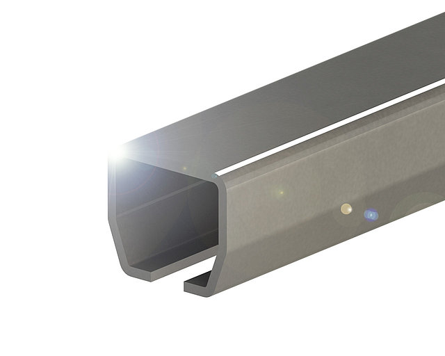
Track profiles with zinc-magnesium coating
With our new generation of track profiles, we launch many advantages.
Convince yourself how we set new standards for track profiles with an innovative material composition!
Our zinc-magnesium coated track profiles, also known as fine sheets, demonstrate significantly better corrosion resistance in many applications compared to fine sheets with conventional zinc coatings.
In addition, zinc-magnesium coatings provide increased protection at cut edges and scratches due to their almost "self-healing" effect.
Advantages of our track profiles with zinc-magnesium coating:
- Excellent corrosion protection, especially in salty environments
- Ability to "self-heal" at cut edges and scratches
- Harder surface with lower abrasion
- Consistent zinc-magnesium thickness on both inner and outer surfaces
- Extended lifespan and usability of the products
- Environmentally friendly and energy-efficient products
1. First, please determine the weight of your gate, if it is not already known. Feel free to use our table as a planning aid for this purpose.
Material weights of panels and solid wood panels, all values in kg per square meter (considering wood moisture content of approximately 8%).
| Material | Material thickness | |||
|---|---|---|---|---|
| 1m² at 16mm | 1m² at 19mm | 1m² at 25mm | 1m² at 40mm | |
| Raw particleboard | 10,03 | 11,91 | 15,67 | 25,07 |
| Coated particleboard | 10,87 | 12,91 | 16,99 | 27,18 |
| MDF | 12,60 | 14,96 | 19,68 | 31,49 |
| Strip, Gaboon deck | 6,84 | 8,13 | 10,70 | 17,11 |
| Birch plywood | 11,22 | 13,33 | 17,54 | 28,06 |
| Spruce three-layer board | 7,24 | 8,60 | 11,32 | 18,11 |
| Solid beech | 11,28 | 13,39 | 17,61 | 28,19 |
| Solid European maple | 10,69 | 12,70 | 16,71 | 26,74 |
| Solid oak | 11,34 | 13,47 | 17,72 | 28,36 |
| Solid larch | 9,69 | 11,51 | 15,14 | 24,23 |
| Solid pine | 7,83 | 9,30 | 12,23 | 19,58 |
| Solid alder | 8,33 | 9,90 | 13,03 | 20,84 |
| Solid European cherry | 9,34 | 11,09 | 14,59 | 23,35 |
| Solid elm | 11,22 | 13,32 | 17,53 | 28,04 |
| Solid ash | 10,78 | 12,80 | 16,84 | 26,95 |
| Solid European walnut | 11,62 | 13,80 | 18,16 | 29,05 |
| Solid locust | 12,26 | 14,56 | 19,16 | 30,65 |
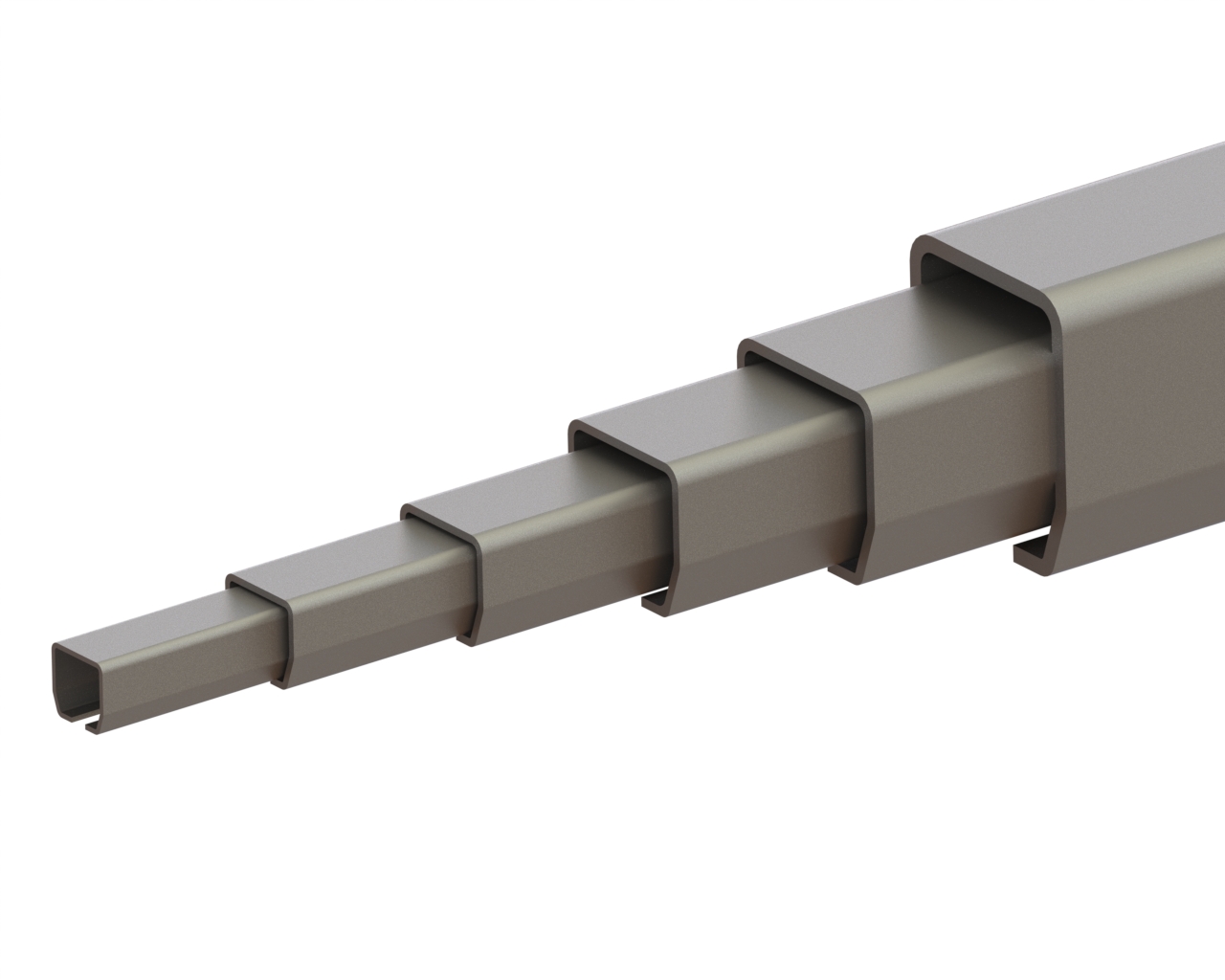
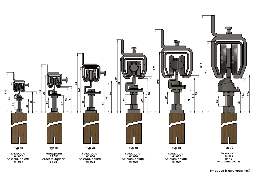
2. Once you have determined your gate weight using the table, you can select the appropriate type of fitting.
Our fittings are divided as follows:
- Type 10 = up to 80 kg
- Type 30 = up to 180 kg
- Type 40 = up to 400 kg
- Type 50 = up to 750 kg
- Type 60 = up to 1200 kg
- Type 70 = up to 2000 kg
These types serve as a guide, allowing you to match the appropriate accessories as well.
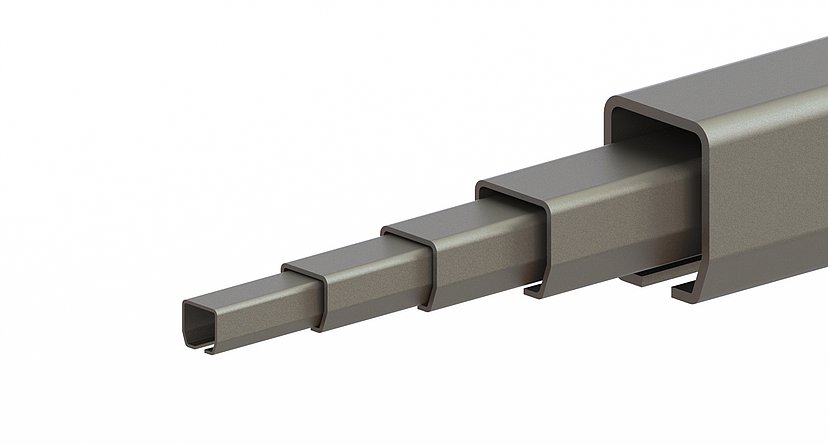
3. After determining the appropriate type for your gate weight, you can choose the rail in the desired length. Typically, the length is twice the width of the door.
With the identified type, you can also select the corresponding accessories such as roller apparatus, connecting sleeves, rail stoppers, fastening sleeves and the bottom guide. An overview of the options is available in our table.
For specific details on each accessory, please refer to the respective product descriptions.
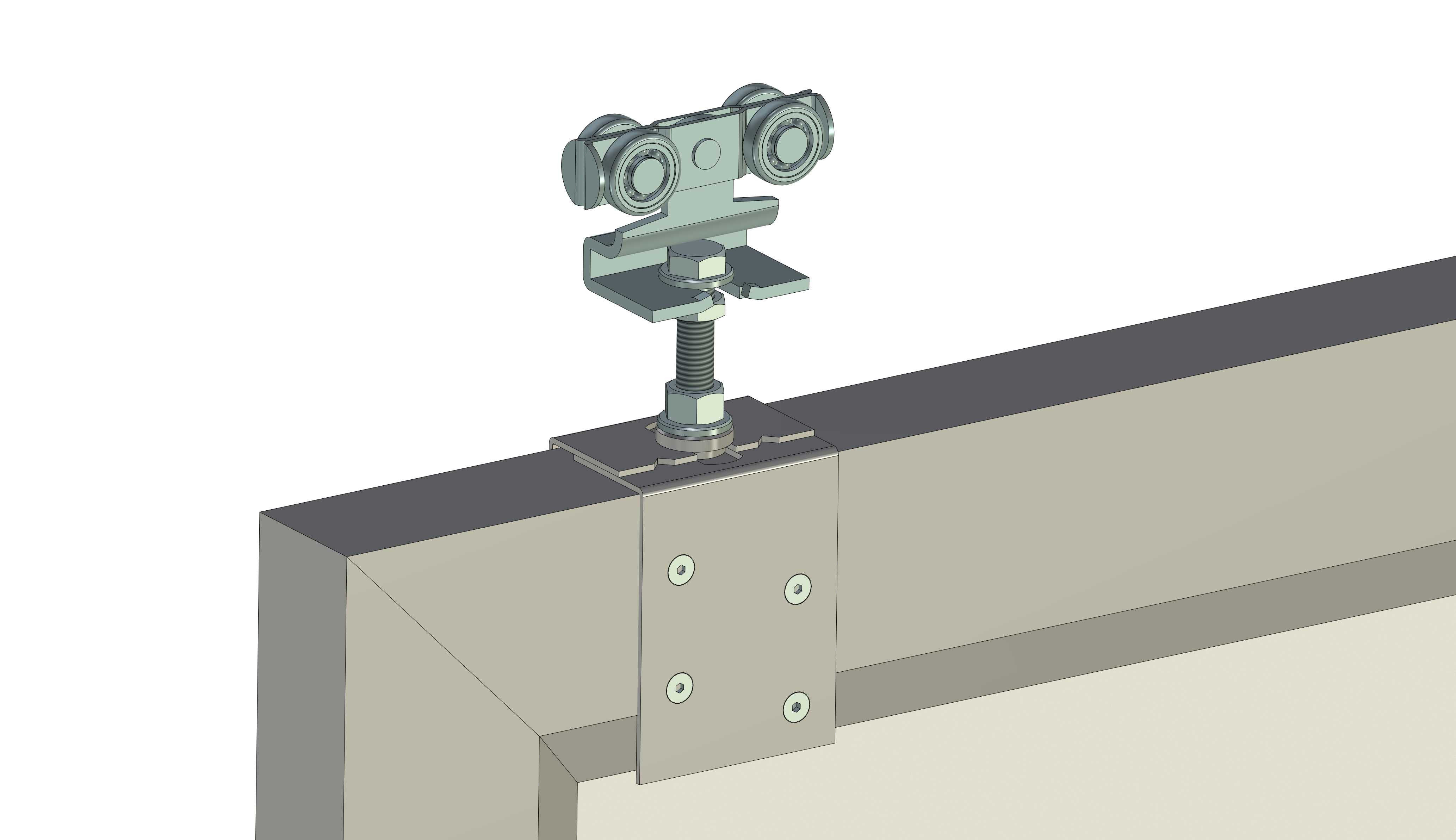
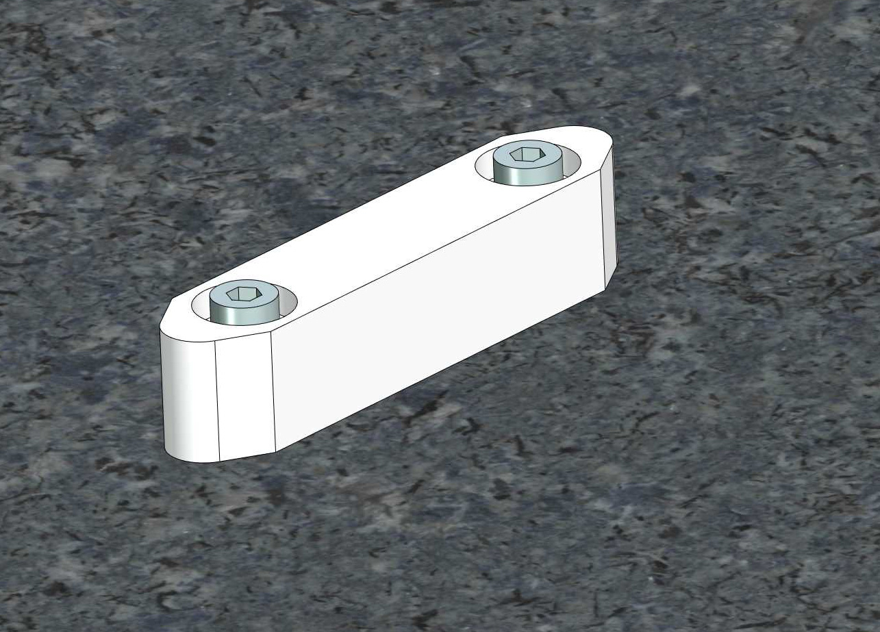
Roller apparatus:
- The roller apparatus runs in the track and supports the door with the help of the screw plate or adjustable screw bracket.
- Only two roller apparatus are required per door.
- CAUTION - Half of the door weight must not exceed the specified maximum load of a roller apparatus.
- In general, never use more than two roller apparatus per gate.
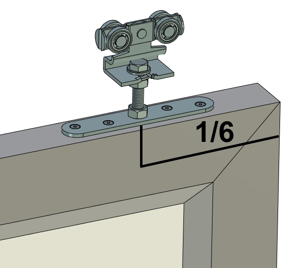
- The optimal fastening should be at 1/6 of the respective door outer edge (see figure on the left).
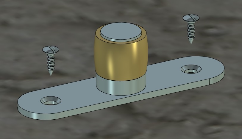
Screw plate: This plate is used to attach the roller apparatus to the door and it is mounted on the door leaf. Two screw plates are required per door. The plate is suitable for solid wood.
Screw bracket: The same applies to the bracket as with the plate. The bracket, however, is especially suitable for wood with a soft core or for pressed wood panels.
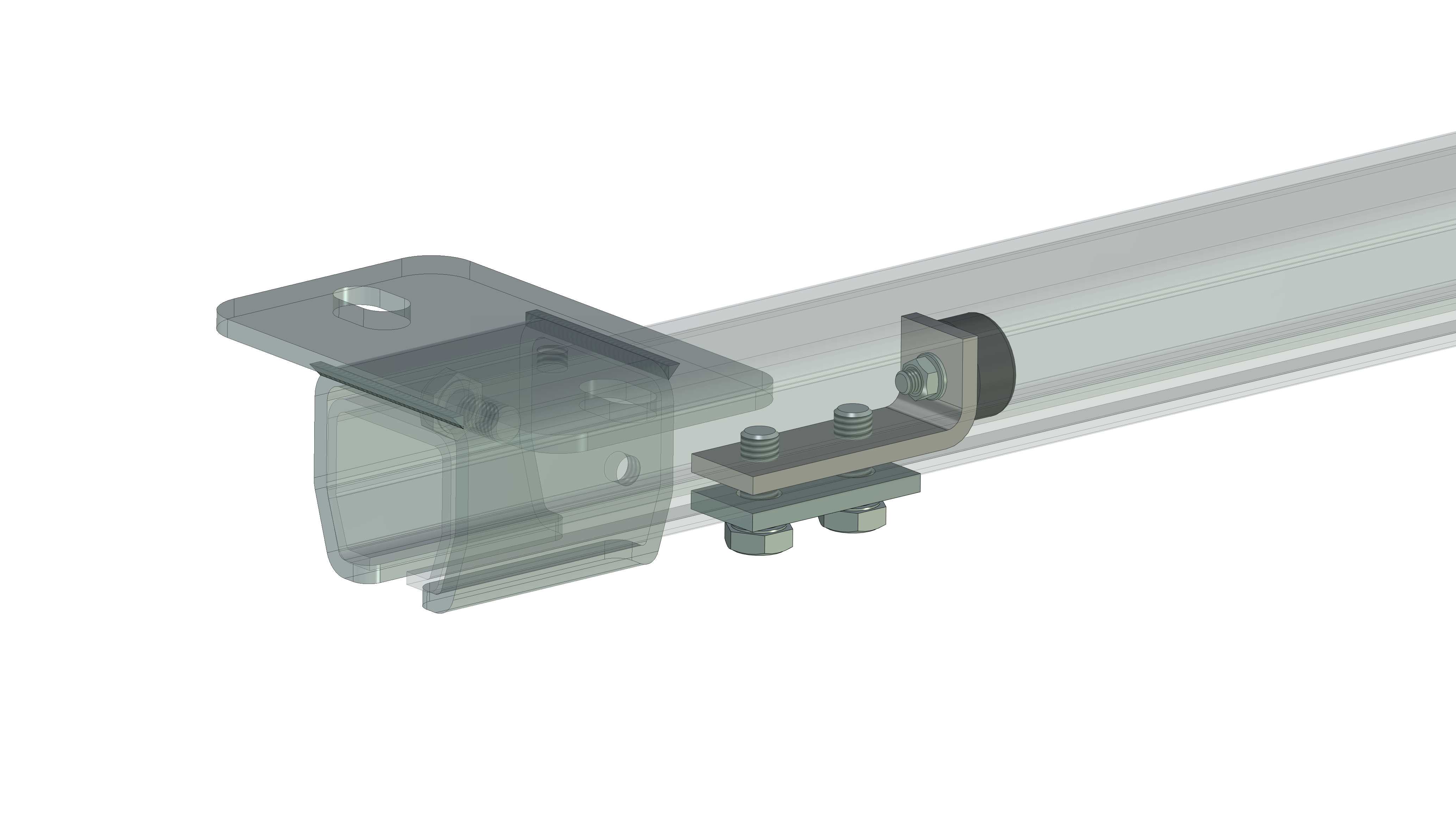
Rail stopper:
The stoppers are mounted at both ends of a track or a track system. Their task is to limit the travel path of the roller apparatus. In general, two stoppers per door are recommended.
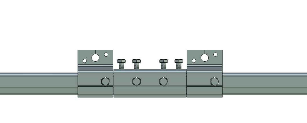
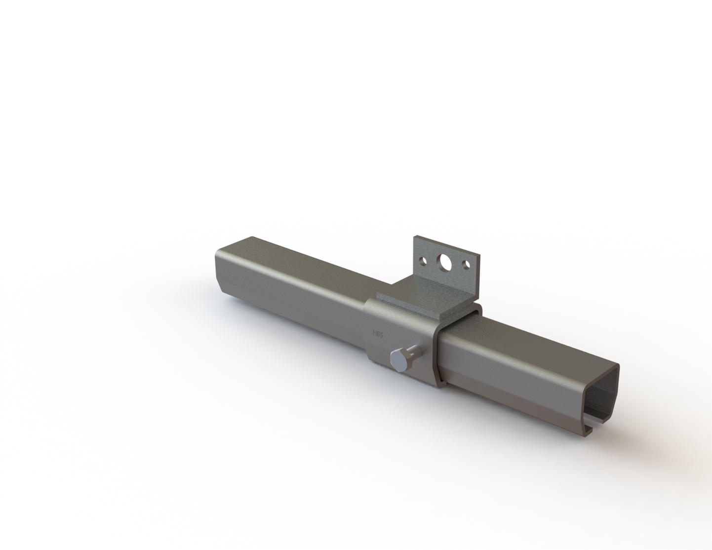
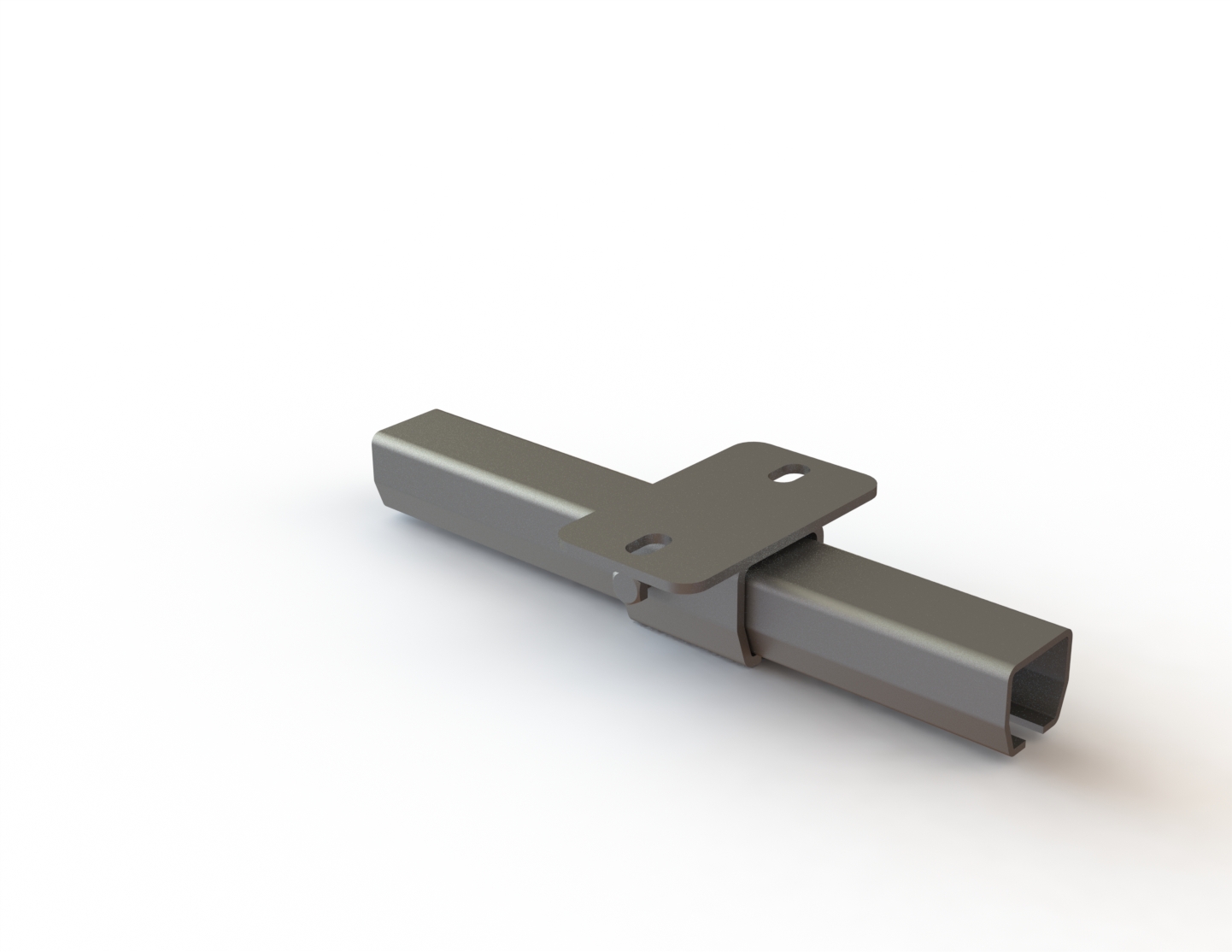
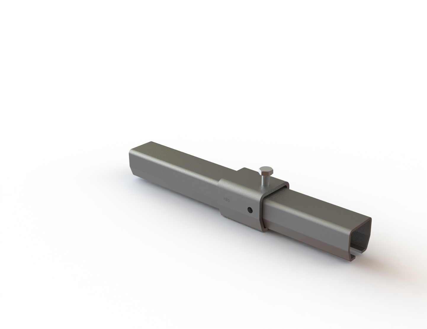
Connection sleeve: Using the connection sleeve, you can join two tracks at their ends. This allows you to achieve different lengths without welding. On both sides of the connection sleeve, one of the previously mentioned sleeves must be mounted to absorb the force.
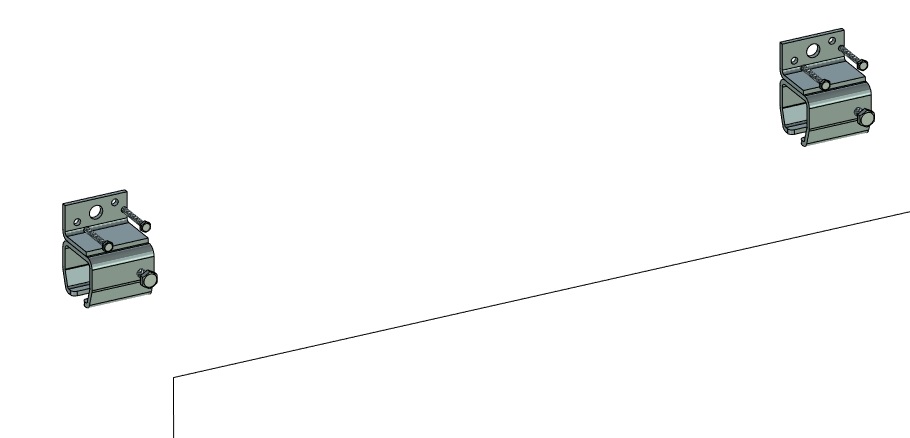
Wall sleeve
The galvanized wall sleeve supports the running track. You can attach it directly to a vertical wall.
Maximum distance between 2 sleeves: 750 mm.
Ceiling sleeve
The galvanized ceiling sleeve supports the running track. You can attach it directly to a horizontal ceiling (beam).
Maximum distance between 2 sleeves: 750 mm.
Weld-on sleeve
The weld-on sleeve is not galvanized. It supports the running track. You can weld the weld-on sleeve directly onto your existing steel structure.
Maximum distance between 2 sleeves: 750 mm.
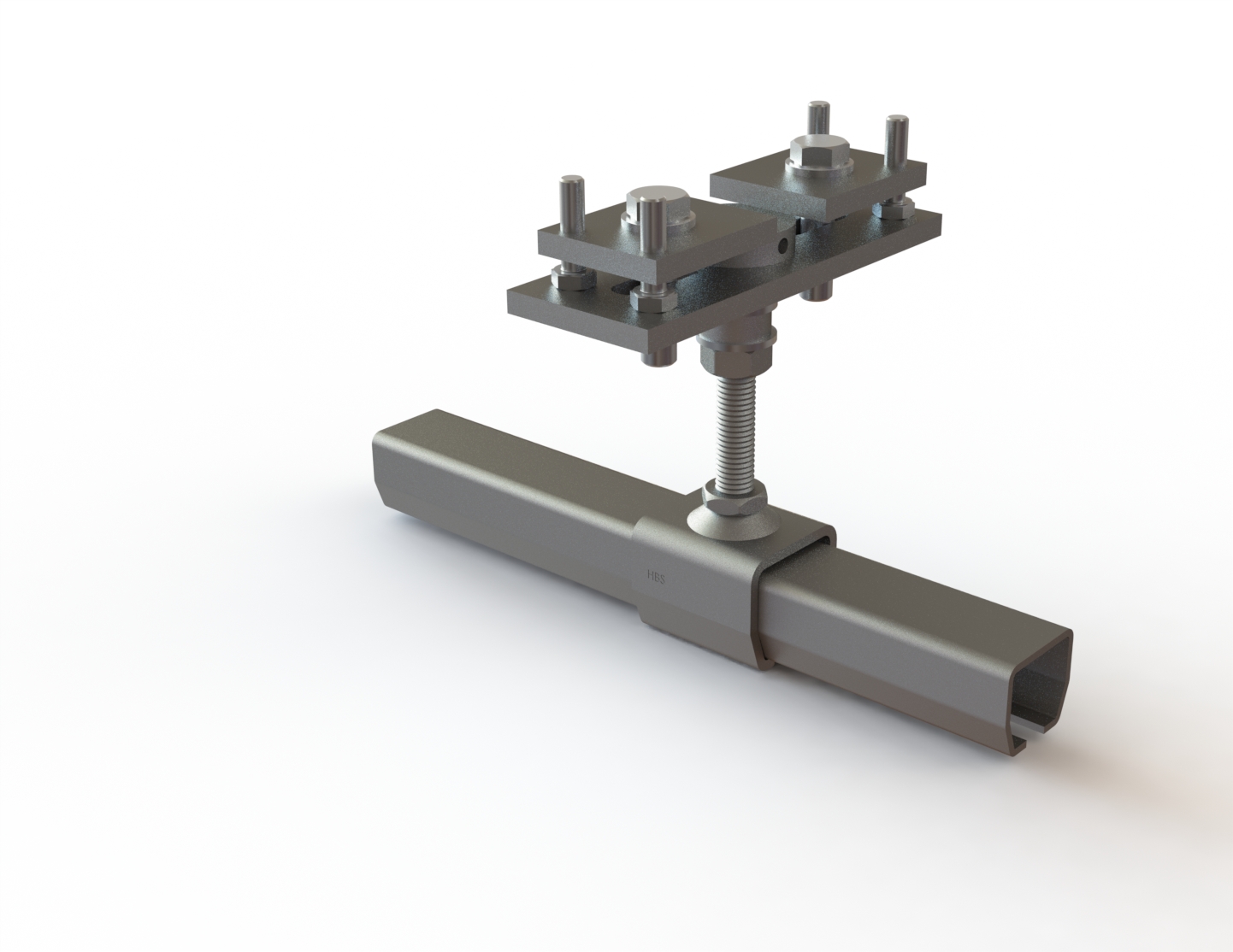
Height-adjustable sleeve
In combination with the angle brackets or the double rail supports, this sleeve achieves the best possible alignment of the rail - both horizontally and vertically.
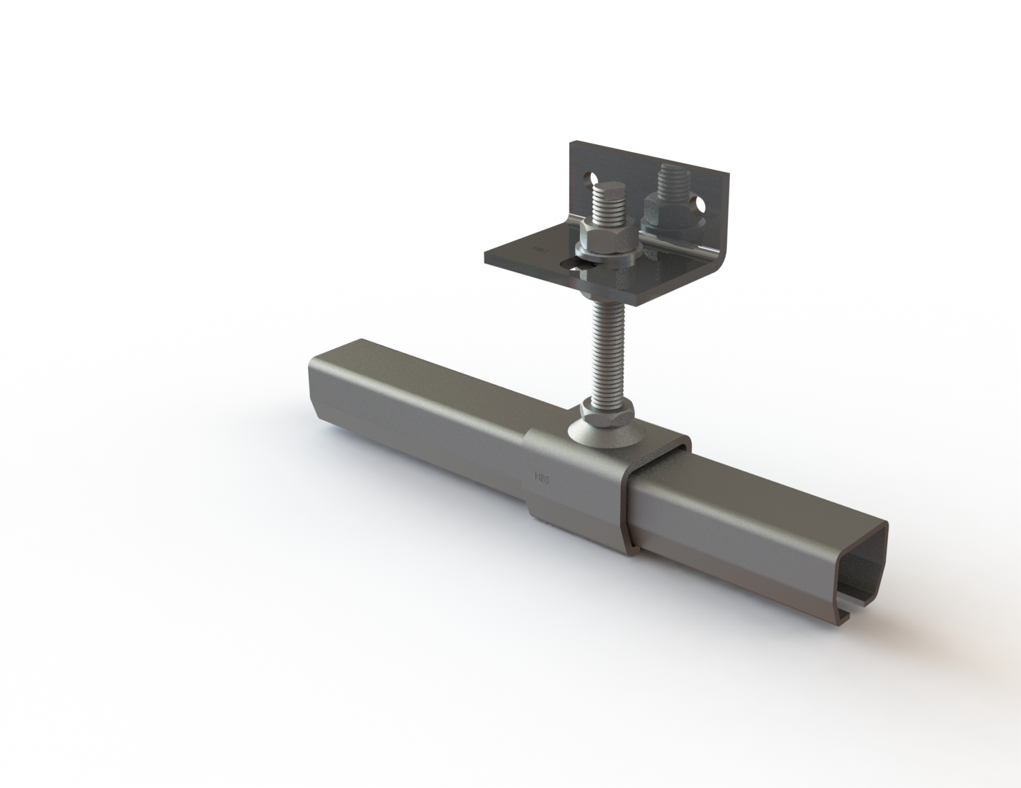
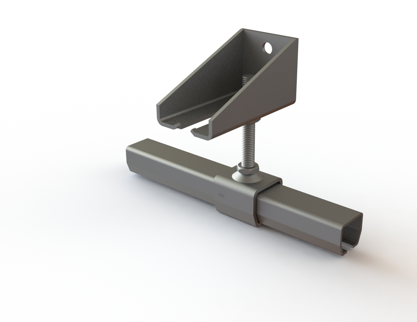
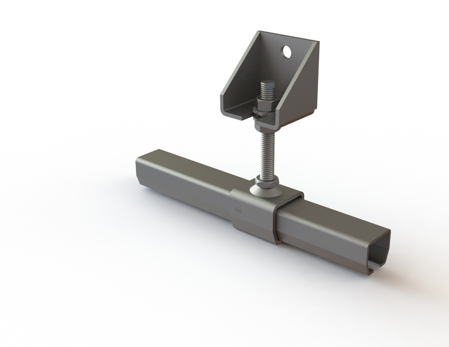
Angle bracket
You can directly attach the galvanized angle bracket to a vertical wall. It accommodates the height-adjustable sleeve. Now you can adjust the height-adjustable sleeve horizontally and vertically within the angle bracket.
Maximum distance between 2 sleeves: 750 mm.
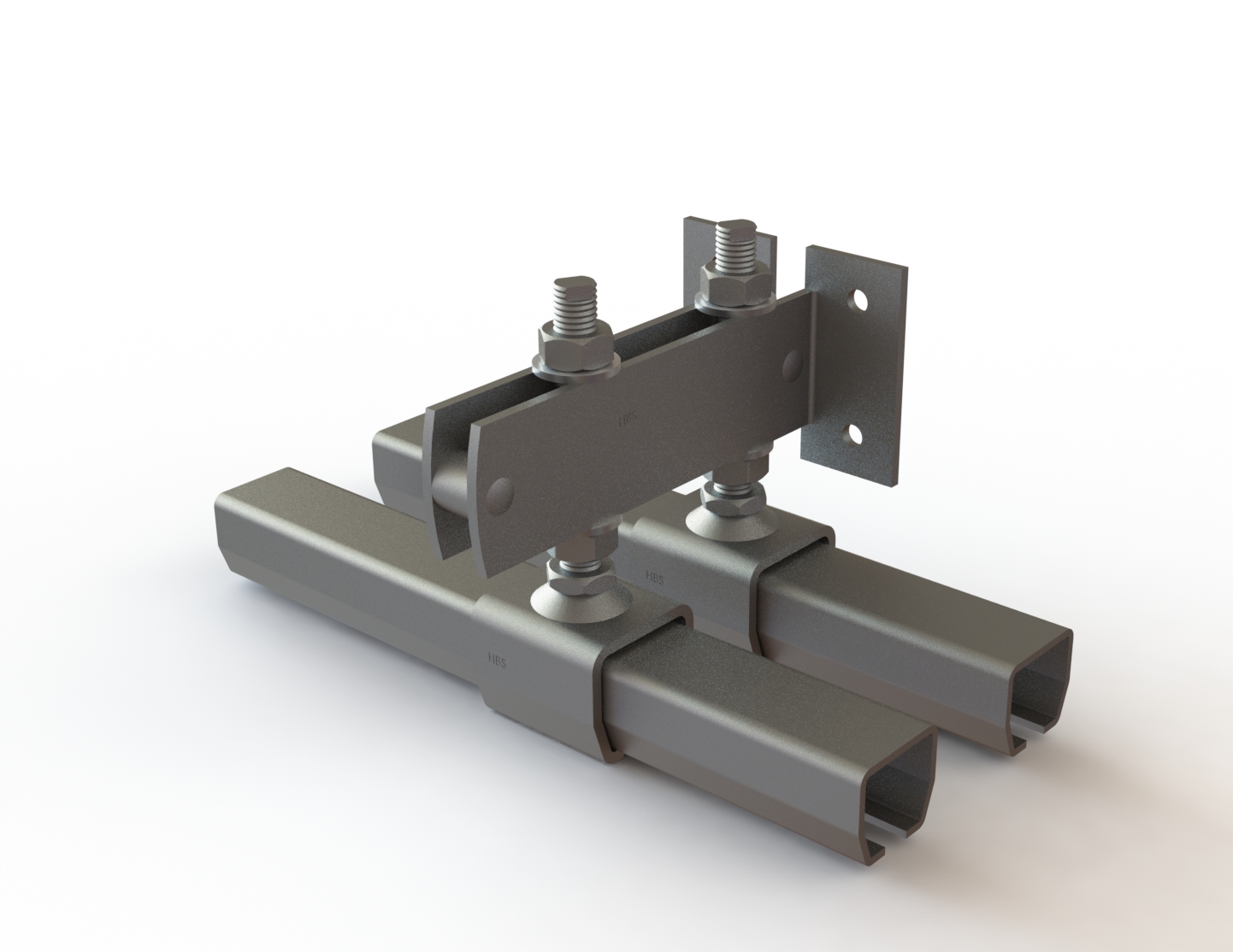
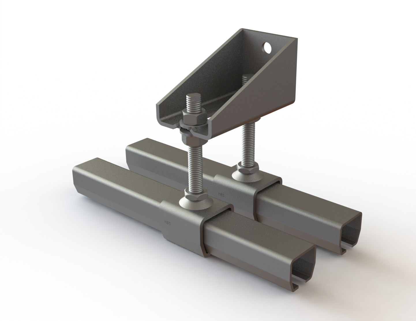
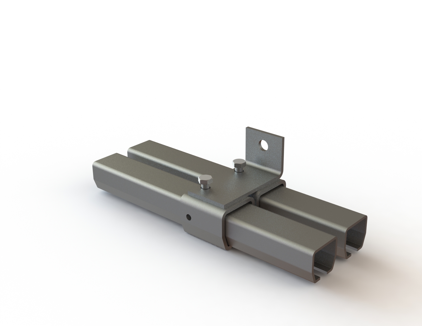
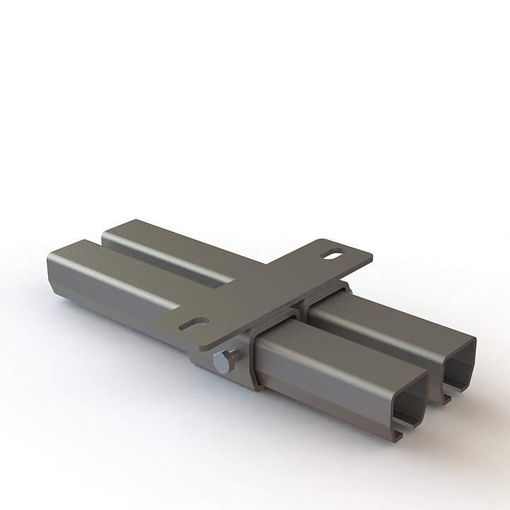
Double rail support
In this rail support, you can mount two height-adjustable sleeves side by side. This way, you could, for example, realize two doors or gates running in front of each other.
Double wall sleeve
The galvanized wall sleeve supports the running tracks. You can attach it directly to a vertical wall (beam). With the double wall sleeve, you could realize two doors running in front of each other. However, please consider the maximum possible door thicknesses before choosing the sleeve.
Maximum distance between 2 sleeves: 750 mm.
Double ceiling sleeve
The galvanized double ceiling sleeve supports the running tracks. You can attach it directly to a horizontal ceiling (beam). With the double ceiling sleeve, you could realize two doors running in front of each other. Please consider the maximum possible door thicknesses before choosing the sleeve.
Maximum distance between 2 sleeves: 750 mm.
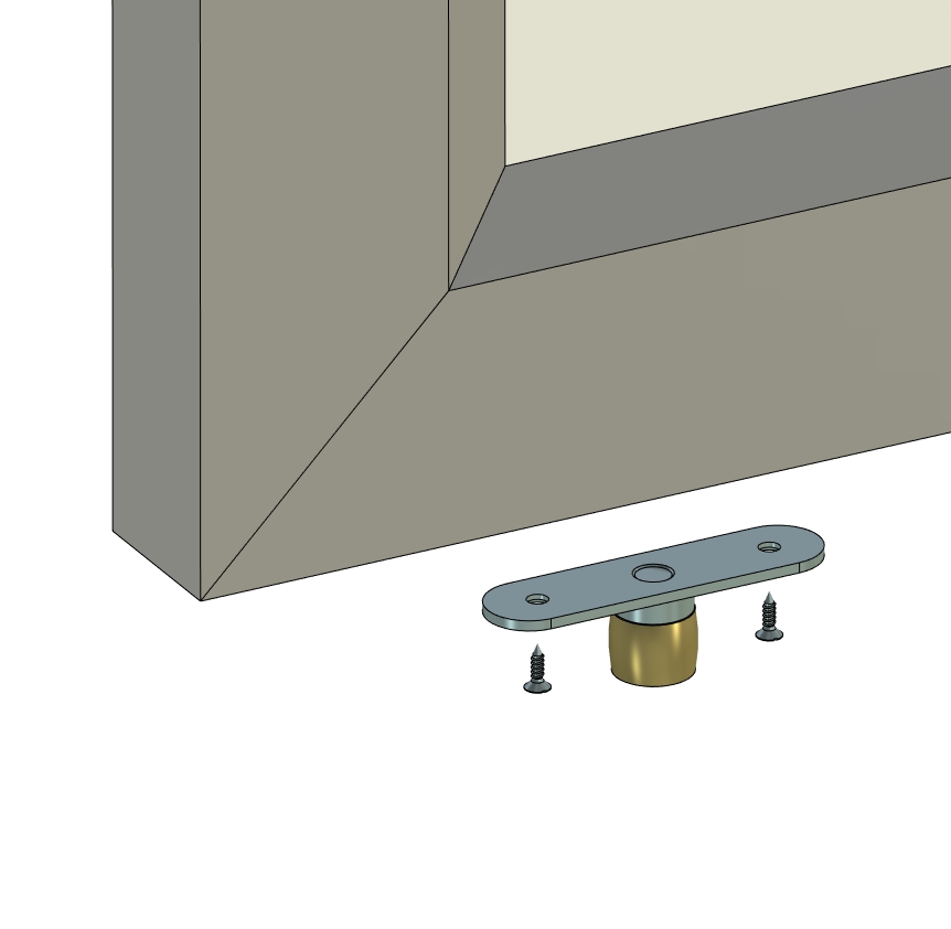
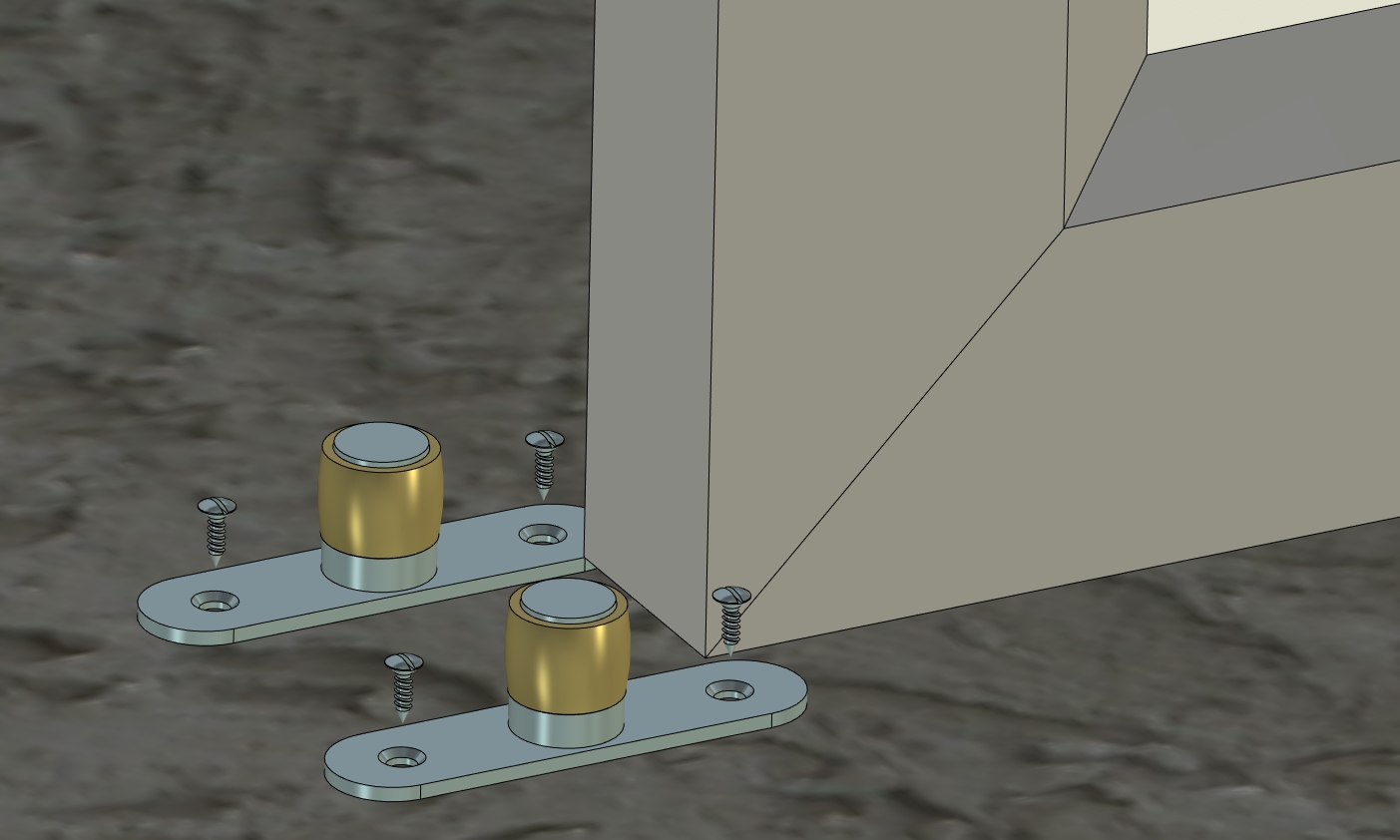
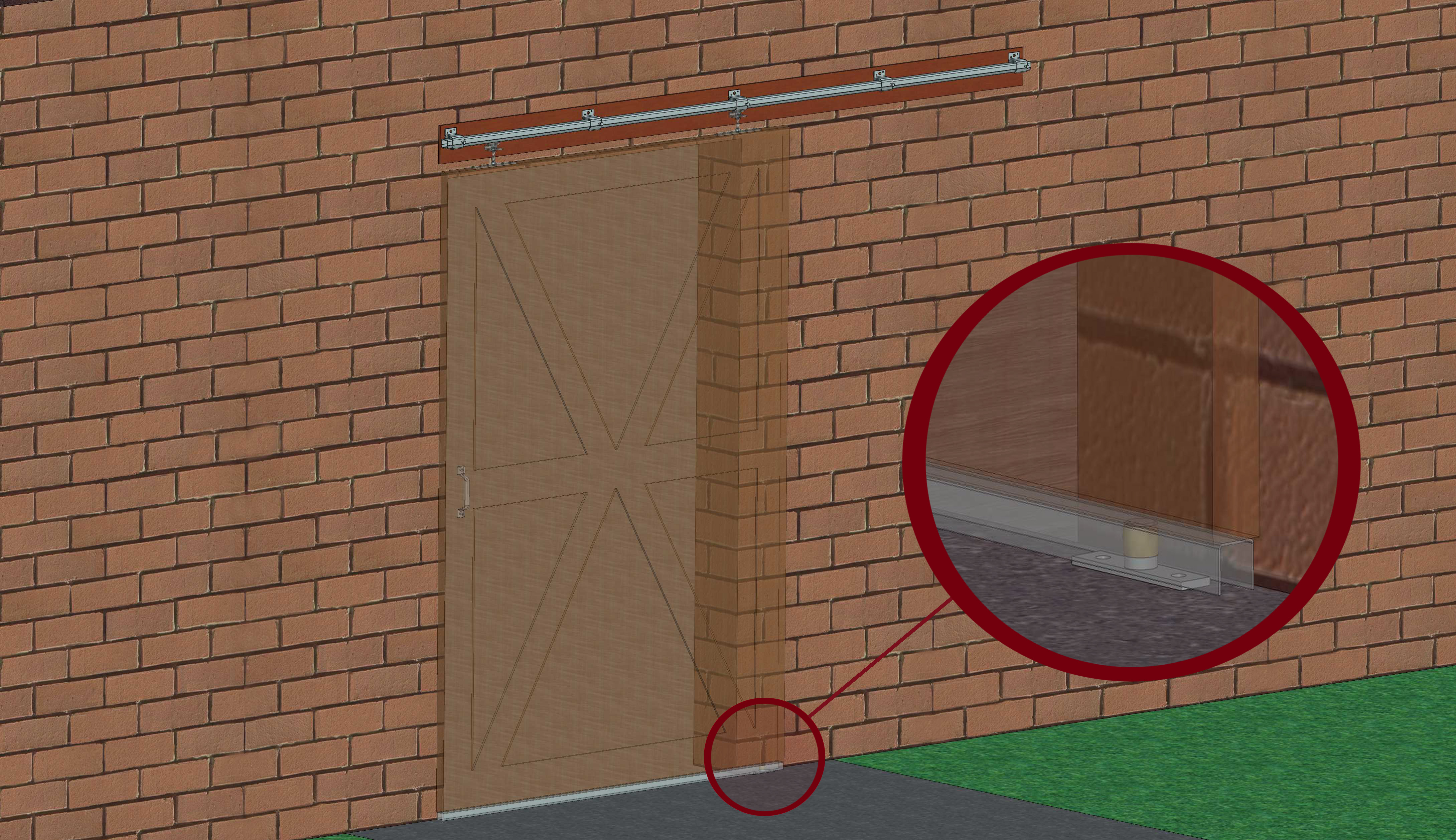
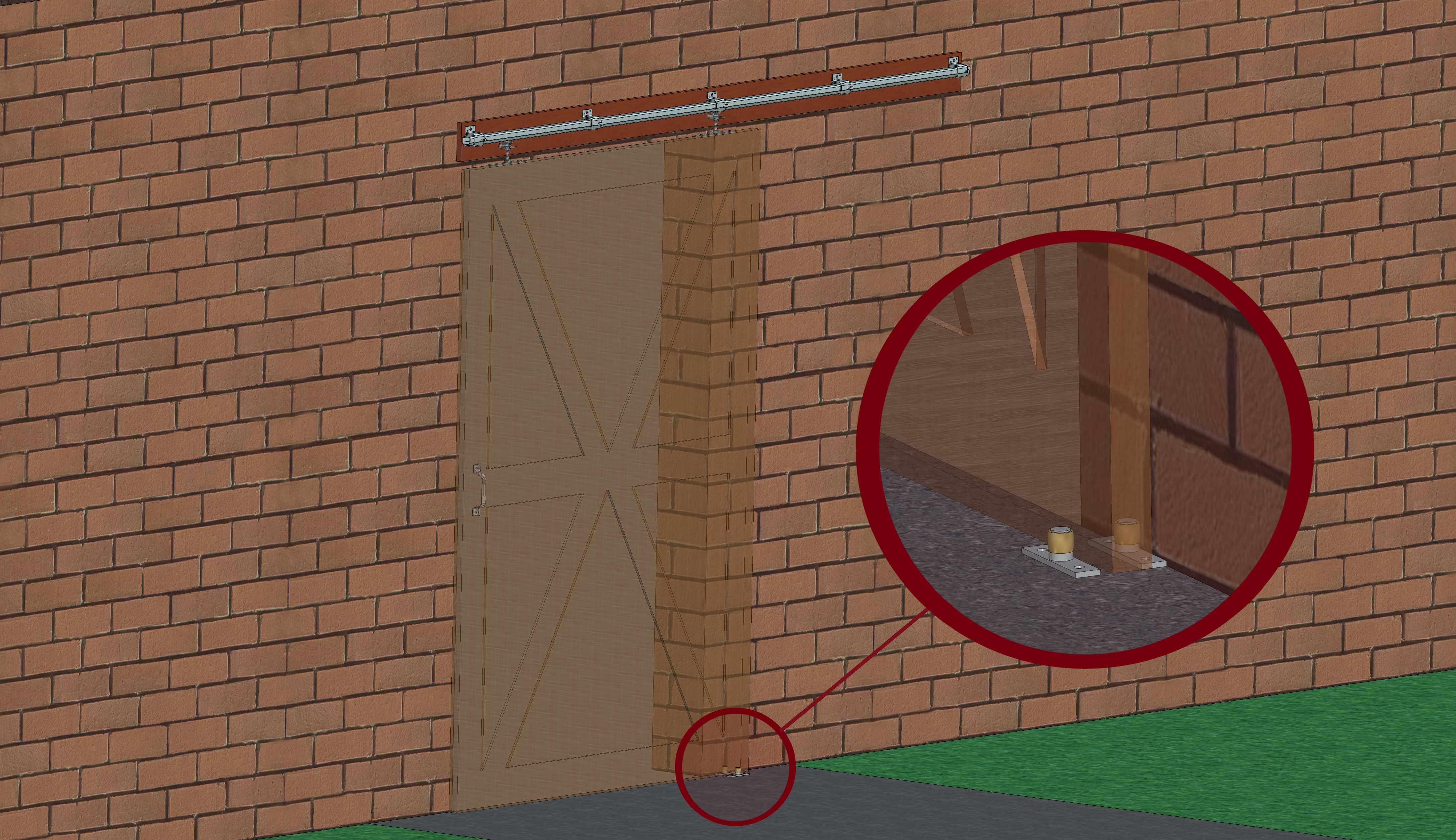
Guide roller / glide: The guide rollers or plastic gliders are attached to the floor in front and behind the gate, guiding it and preventing it from swinging. Therefore, two guide rollers or gliders are needed per gate (see Figure Variant 1).
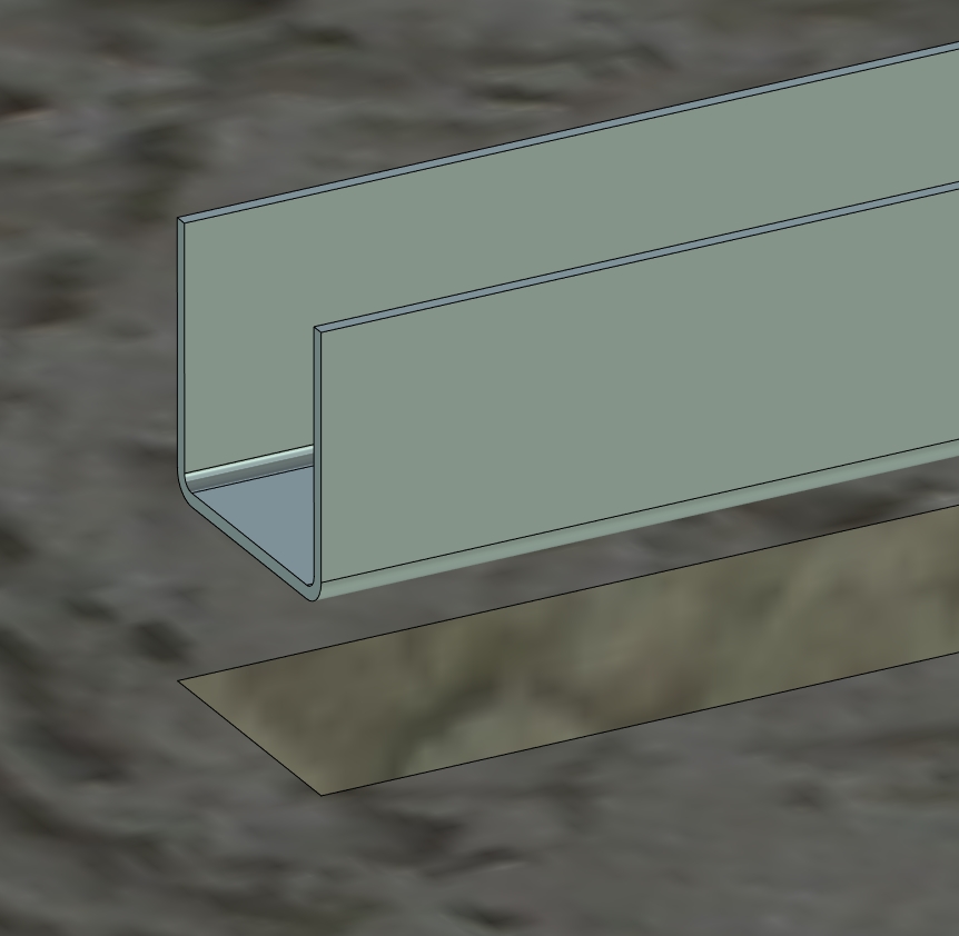
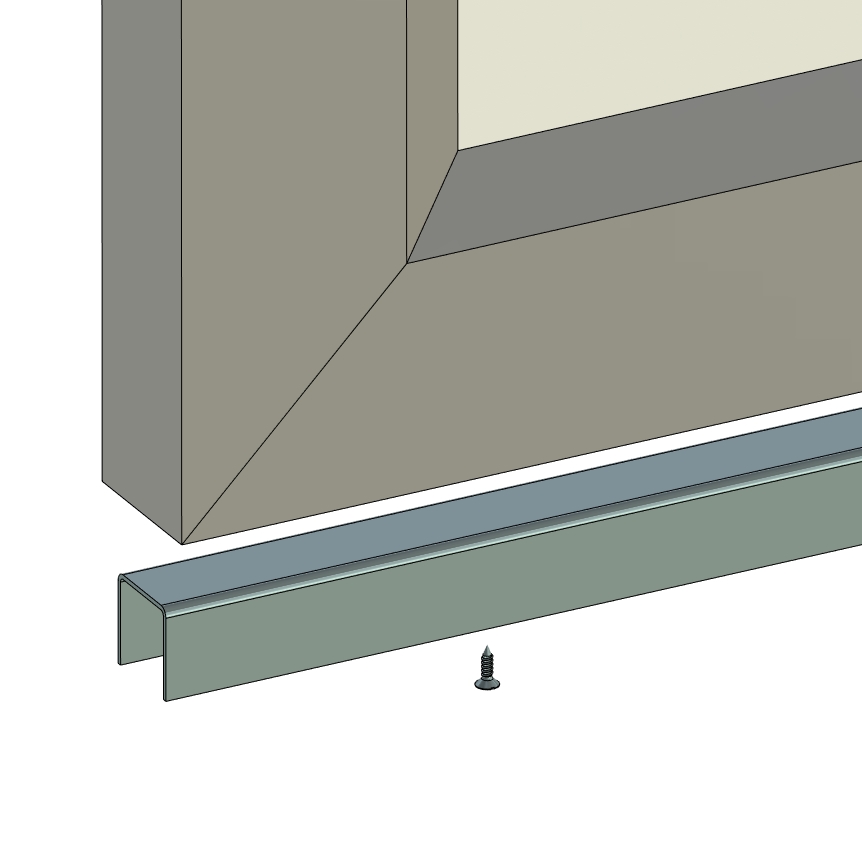
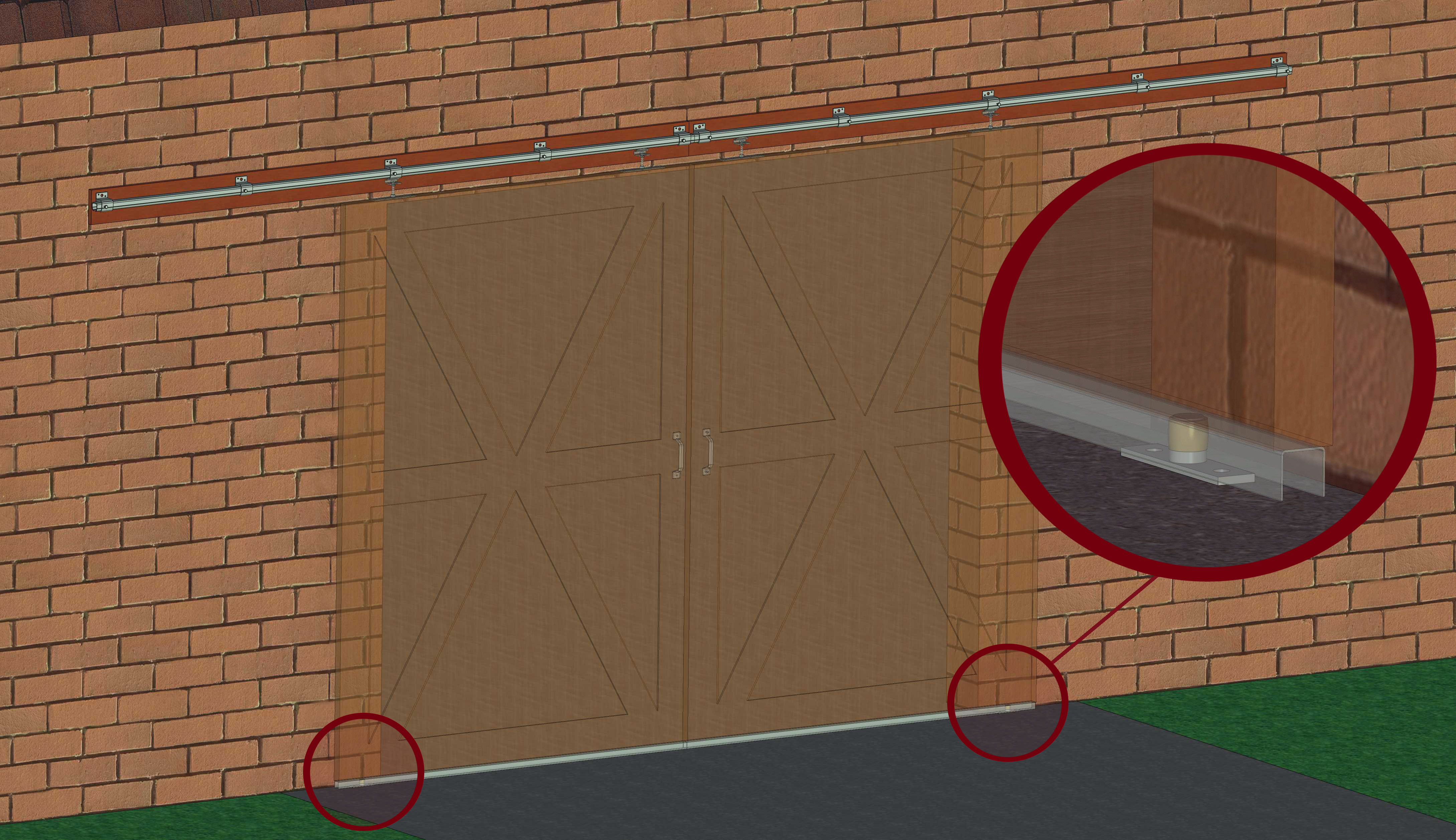
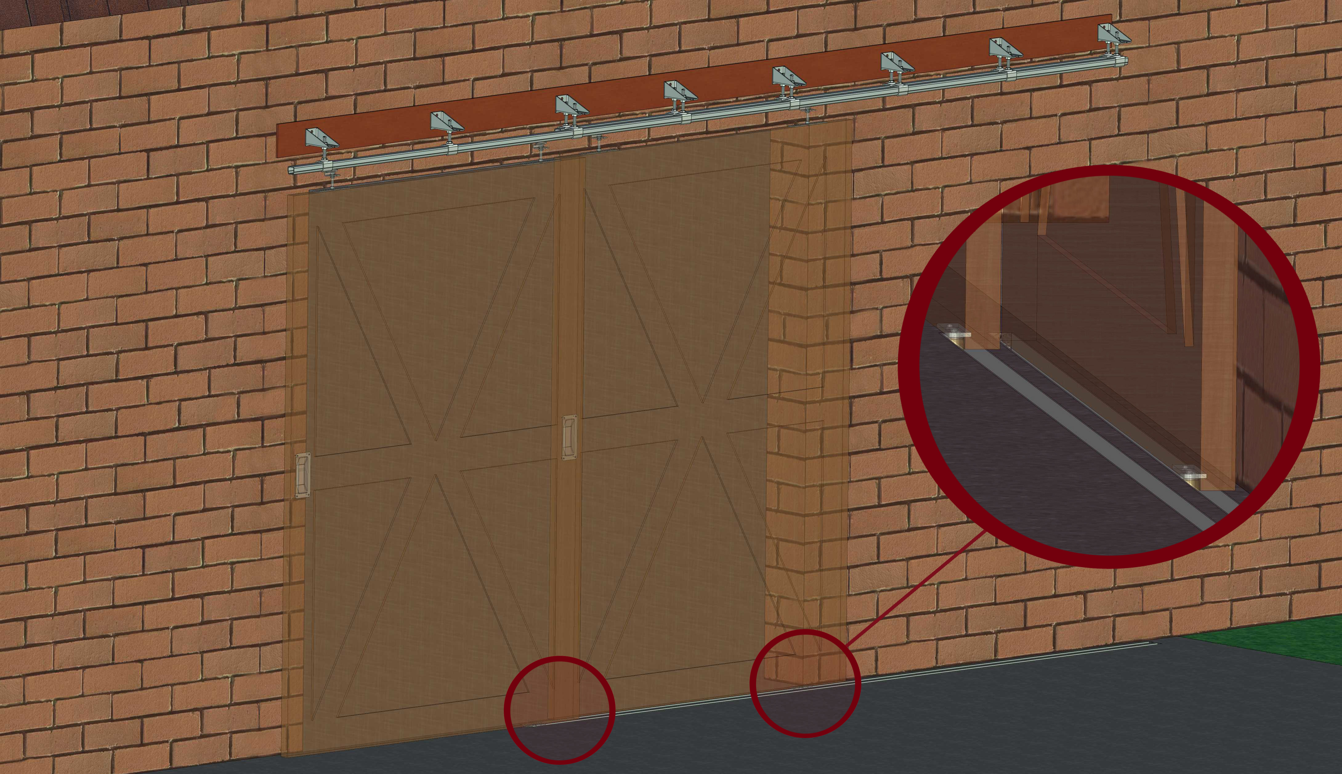
Guide rail: The rail, combined with a suitable guide roller or glider, provides an alternative to the above solution with two guide rollers or gliders. In this case, the rail is mounted with the opening facing downward at the bottom of your gate. The guide roller or glider is then attached parallel to it on the floor, guiding it within the rail (see Figure Variant 2).
Gate weight - Number of gates
What you should know about sliding gate fittings C profile:
- The number of gates has no impact on the maximum load capacity of the track.
- It is also crucial not to exceed the maximum load capacity of the selected roller apparatus. Adhere to the attachment points on the track, spaced every 750 mm.
If you still have questions after using our planning guide, feel free to contact us by phone or through our contact form. You can also check our FAQ section for more information:
The running track should be secured every 750 mm using the sleeves. For example: Running track 2 m = 4 sleeves / Running track 3 m = 5 sleeves / Running track 6 m = 9 sleeves.
The sliding door stopper ensures a clean closure of your sliding door. The stopper is mounted in a way that the roller carriage is stopped just before the door reaches the wall. This protects your door and ensures a long lifespan of the structure.
If more than two roller carriages are used per door, the door may start to wobble, or the ball bearings in the running wheels may be unevenly loaded, leading to potential failure. In both cases, an unstable operation or damage to the hardware can occur.
The running tracks are treated with a Sendzimir galvanization with an additional zinc-magnesium layer. The advantages at a glance:
- Excellent corrosion protection
- Ability to 'self-heal' at cut edges and scratches
- Extended life and usability of the products
- Conservation of valuable resources
- Environmentally friendly and energy-efficient products

Accessories such as sleeves and roller carriages have a galvanized coating.
Mounting a running track without matching sleeves is generally not recommended. However, if it is unavoidable due to space constraints, the running track can be drilled and countersunk on-site, and then attached with suitable screws and anchors. It is important in this case that the screw head is completely countersunk within the track so that the roller carriage is not obstructed or stopped on its path. The mounting should be done at least every 500 mm in this case.
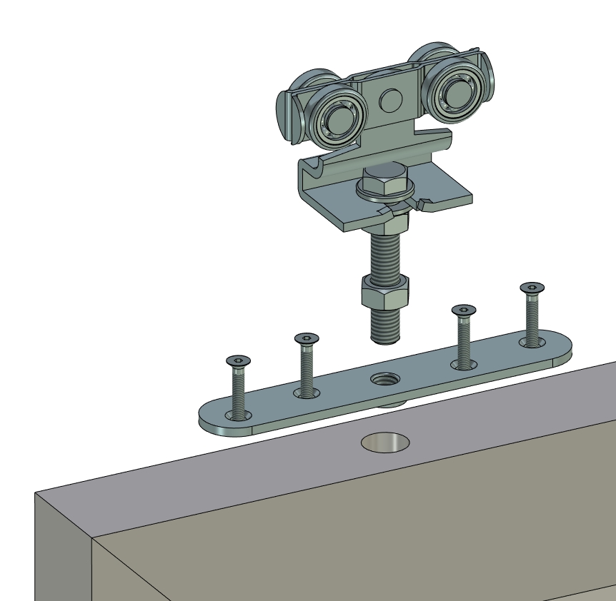
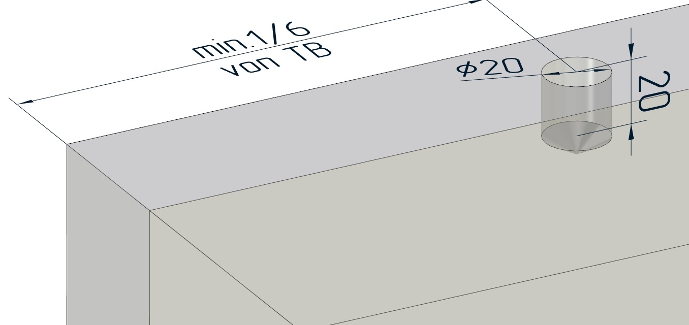
The roller carriages or the screw-on plates or tabs should be installed at the upper edge of the door leaf at 1/6 of the door width. See illustration:
For types 10 and 30, the screw-on plates have a bent thread on the underside due to the lower material thickness of the plates. For this, a hole should be made at the upper edge of the door leaf. The decisive dimension is 'o' in the respective dimension table. Example illustration for Type 30:
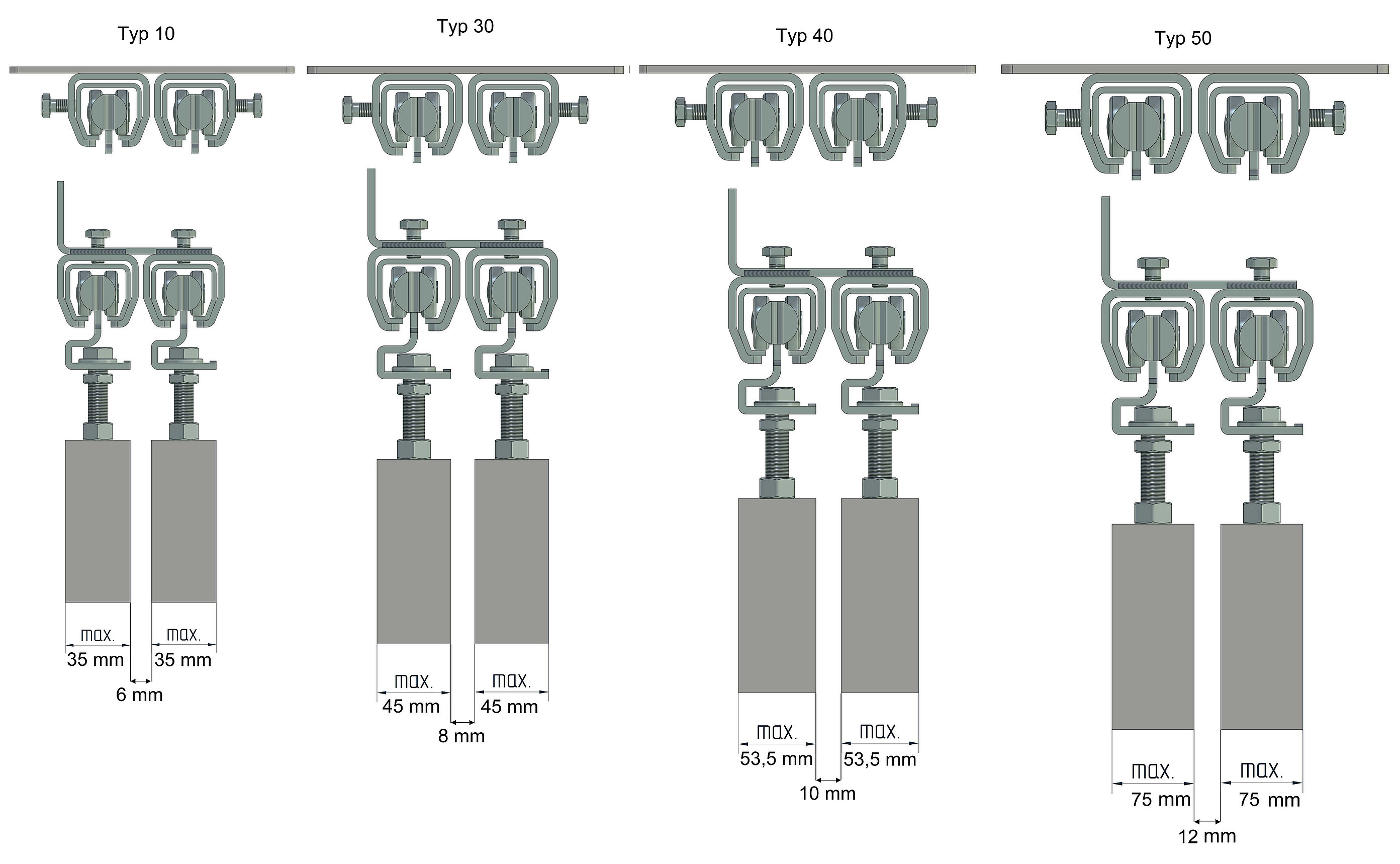
In this case, it is especially important to consider the thickness of the door leaves as well as the choice of suitable fastening to ensure that the project can be realized. Below, you will find an illustration that will assist you in the selection:
The installation of a lower guide should always be carried out. There are many different options:
If not already known, determine the weight of your door. As a planning aid, you can use the following table: Material weights of panels and solid wood panels, all values in kg per square meter (considering wood moisture content of approximately 8%). The table is for guidance only; all information is provided without guarantee. Additionally, it should be noted that the door must have the following minimum thickness for the respective rail type to ensure there is enough material for the screw-on plate installation: Type 10 min. 30 mm / Type 30 min. 35 mm / Type 40 min. 40 mm / Type 50 min. 45 mm.
| Material | Material thickness | |||
|---|---|---|---|---|
| 1m² at 16mm | 1m² at 19mm | 1m² at 25mm | 1m² at 40mm | |
| Raw particleboard | 10,03 | 11,91 | 15,69 | 25,07 |
| Coated particleboard | 10,87 | 12,91 | 16,99 | 27,18 |
| MDF | 12,60 | 14,96 | 19,68 | 31,49 |
| Strip, Gaboon deck | 6,84 | 8,13 | 10,70 | 17,11 |
| Birch plywood | 11,22 | 13,33 | 17,54 | 28,06 |
| Spruce three-layer board | 7,24 | 8,60 | 11,32 | 18,11 |
| Solid beech | 11,28 | 13,39 | 17,61 | 28,19 |
| Solid European maple | 10,69 | 12,70 | 16,71 | 26,74 |
| Solid oak | 11,34 | 13,47 | 17,72 | 28,36 |
| Solid larch | 9,69 | 11,51 | 15,14 | 24,23 |
| Solid pine | 7,83 | 9,30 | 12,23 | 19,58 |
| Solid alder | 8,33 | 9,90 | 13,03 | 20,84 |
| Solid European cherry | 9,34 | 11,09 | 14,59 | 23,35 |
| Solid elm | 11,22 | 13,32 | 17,53 | 28,04 |
| Solid ash | 10,78 | 12,80 | 16,84 | 26,95 |
| Solid European walnut | 11,62 | 13,80 | 18,16 | 29,05 |
| Solid locust | 12,26 | 14,56 | 19,16 | 30,65 |
To assist you or your customers in planning, an overview of installation heights has been created. The illustrations show the maximum heights from the top of the door to the top of the wall sleeves for Type 10 - 70. The dimensioned screws indicate by how many millimetres the installation height can still be reduced. In areas with spatial constraints, preliminary planning can be carried out, for example, defining the door height.
If you require further information, please use our contact form!